Home / Blog / How to Build a Navigation System for GNSS-Denied Environments
How to Build a Navigation System for GNSS-Denied Environments
A GNSS-denied navigation system is built by combining an inertial measurement unit with the aiding sensors that suit your platform. Choosing the right combination starts with understanding the components. In general, a navigation system consists of an inertial navigation system and the aiding systems that support it. GNSS will not always be there, so in a GPS-denied or GNSS-denied environment the real question is what your system relies on.
ATEŞ Labs Engineering Blog · November 2026 · 7 min read
The Core
Inertial Measurement Unit
The core element of an inertial navigation system is the inertial measurement unit (IMU). IMUs come in different grades: industrial, tactical, navigation and strategic.
Cost grows logarithmically. Industrial IMUs can cost as little as a few dollars, while navigation-grade IMUs can exceed $100K and strategic-grade IMUs $1M.
Inertial navigation cannot be jammed, but by its very nature it "jams itself": it drifts. Inertial navigation systems need a known starting position and rely on initialization systems.
Unaided navigation hardly exists in practice. Aiding units improve navigation performance and provide robustness when GNSS is unavailable.
The Most Common Aid
GNSS
GNSS (GPS, GLONASS, Galileo, BeiDou) is the aid we use most often. Combined with an INS, it is called INS/GNSS. GNSS provides high-accuracy, low-cost navigation worldwide, on land, at sea, in the air and in space. But it is very sensitive to jamming and easy to jam, because by the time GNSS signals reach the receiver they have dropped to the noise floor, or even slightly below it. A simple jammer can easily disrupt them. And then there are spoofers...
Anti-Jam Protection
CRPA
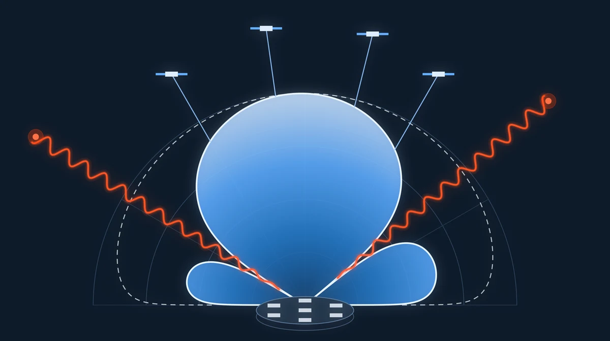
A CRPA (Controlled Radiation Pattern Antenna, also known as Controlled Reception Pattern Antenna) is an anti-jam antenna. Unlike a conventional antenna, it algorithmically estimates the direction of a jammer and shapes its antenna pattern to suppress signals from that direction, while still receiving signals from all other directions.
The number of elements determines how many jammers it can suppress at the same time. The general rule is "number of elements minus one": a 4-element CRPA can suppress jammers from 3 different directions, and an 8-element CRPA from 7.
It can suppress a jamming signal by up to 40–50 dB. However, its effectiveness can drop against very powerful or very numerous jammers.
Absolute Correction
Visual Navigation
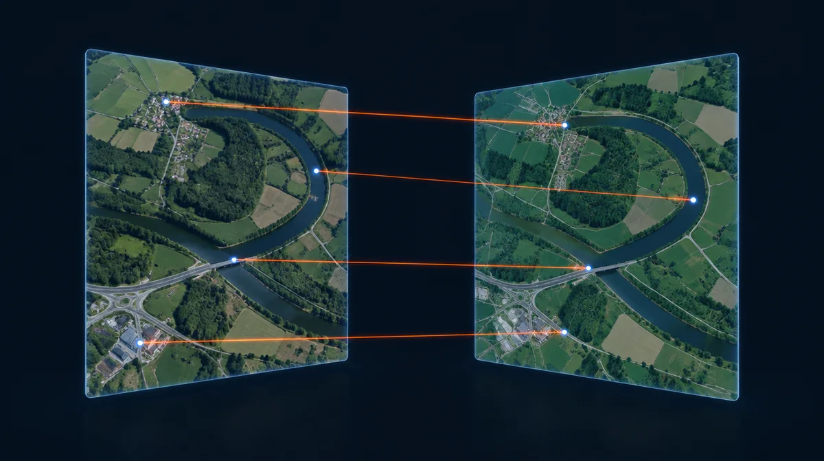
Like GNSS, visual navigation can provide absolute position and attitude corrections. It works by matching camera images against a visual database, just as people do. You are in a taxi in Ankara, thinking you are at Kızılay Square, when you notice you are passing Anıtkabir, Atatürk's mausoleum. You realize, "I had my position wrong; I am actually near Anıtkabir." The logic is very similar.
By matching day and thermal camera imagery, you can make 6DoF position and attitude corrections, but you need sufficiently distinctive patterns. It does not work over open sea, for example. In fog or rain, performance degrades or disappears altogether.
Relative Correction
Visual Odometry
This method is known as VINS (visual-inertial navigation system). Navigation drift is reduced using IMU measurements and the motion of points tracked in the image. It gives no absolute correction, but drift can be brought down to linear levels. It works well on land and can work in the desert, but not at sea.
Air
Pitot
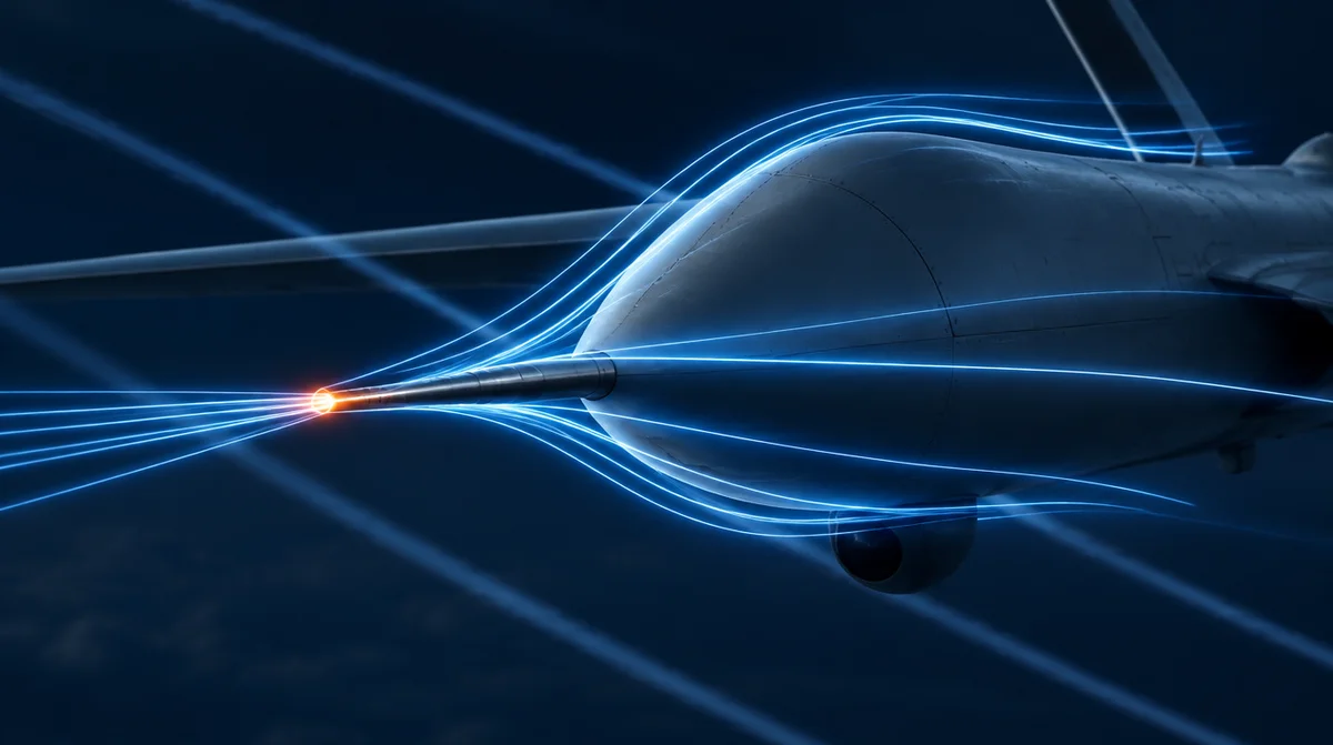
The airspeed sensors commonly used on fixed-wing drones can also serve as a navigation aid. You can estimate wind speed and compute your ground speed from airspeed. Although the measurement error is high, combined with a tactical-grade IMU it can keep error at a reasonable level on flights of around one hour. What counts as reasonable depends entirely on your application.
Sea
Speed Log
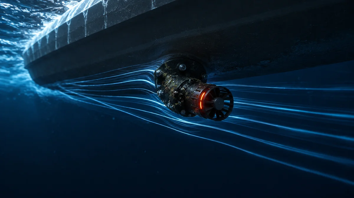
Think of it as the maritime equivalent of airspeed: current is to the sea what wind is to the air. A speed log gives speed through water; you can estimate the current and derive your speed over ground from the log measurement. Like any device used at sea, speed logs are significantly affected by seawater. Regular cleaning improves accuracy, and with a tactical-grade IMU you may be able to navigate for hours without GNSS.
Sea
Doppler Velocity Log (DVL)
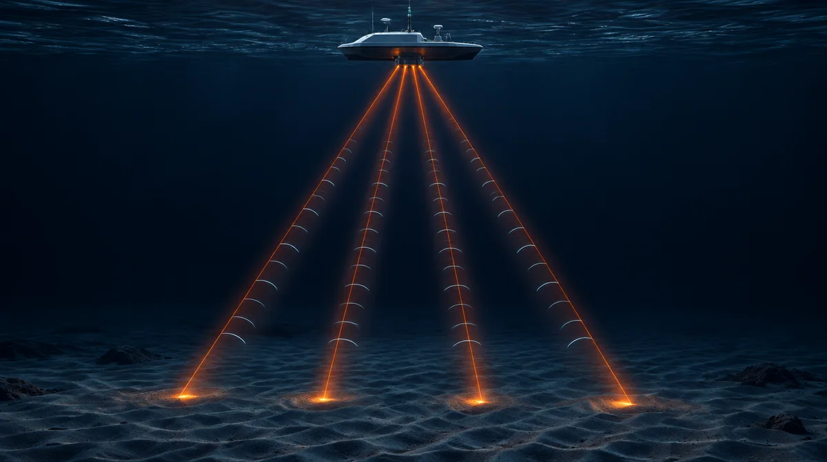
In marine systems, a DVL measures velocity relative to the seabed. You have no current problem, but you do have a range problem. This measured velocity is again used directly as a velocity correction in your navigation filter, reducing drift. Again, with a tactical-grade IMU you can navigate for long periods (> 1 hour) without GNSS.
Land
Wheel Odometry
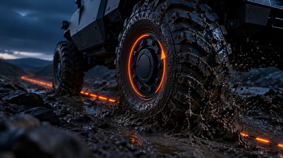
Used on land vehicles, this is the same method familiar from cars, where distance travelled is estimated from wheel rotation: the wheel turned this much, so I travelled this far, and that information feeds the navigation filter. Slip, mud and rough terrain directly affect performance.
All Weather
Radar Odometry
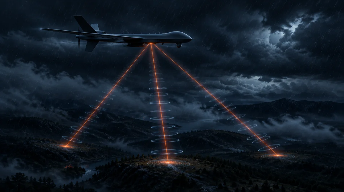
Though less common than other methods, Doppler velocity radars mounted on aircraft can estimate velocity relative to the ground from Doppler measurements. By comparing the velocity estimated by your INS with the measured velocity, you can estimate your error and use it as an update source in your filter. A Doppler velocity radar looking in several directions can provide a 3D velocity correction. The upside of this method is that it works in all weather; the downside is that it reveals your position.
Heading
Compass
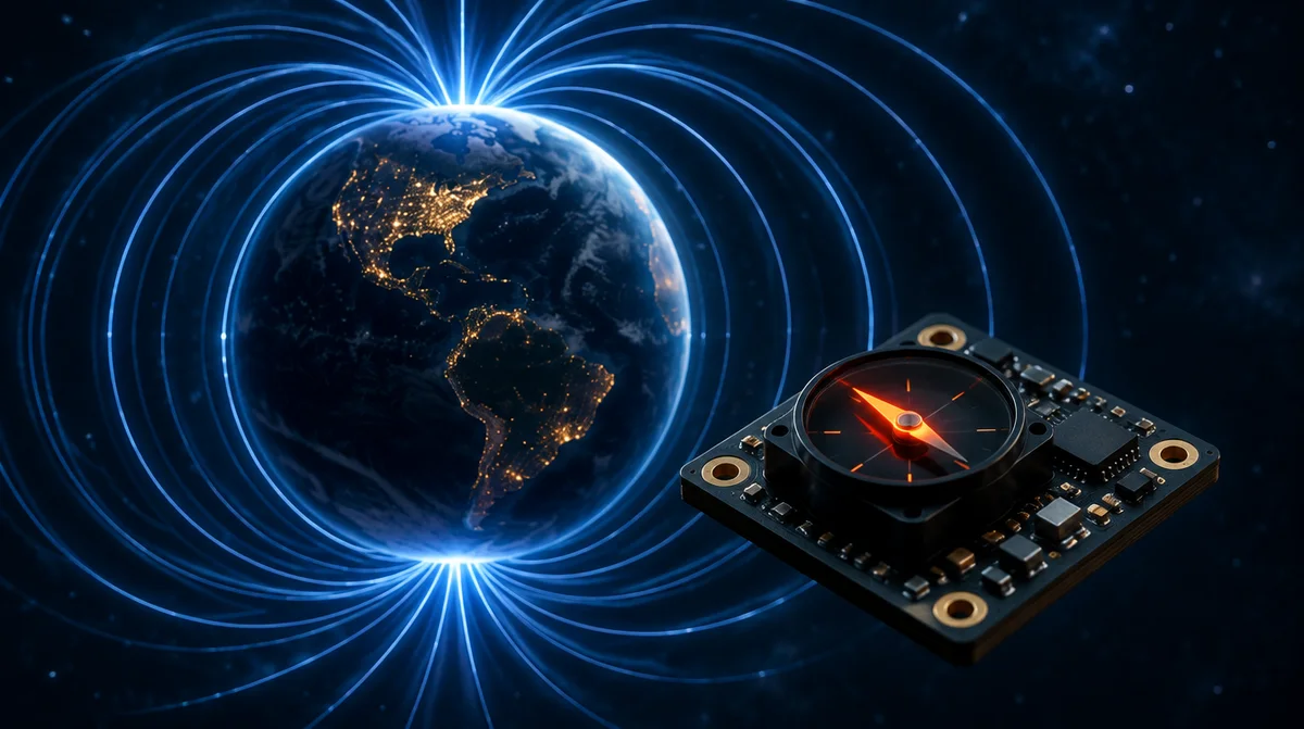
A compass uses Earth's magnetic field to estimate your heading. It is an inexpensive method: for a few tens of dollars, good sensors give you a rough heading estimate. But where you mount a compass matters, and it needs platform-specific calibration. Quantum compasses have also begun to be used for magnetic anomaly detection.
Altitude
Static Pressure Sensor
This sensor supports the altitude channel. It helps you hold a hover and keeps you from hitting the ground. It is commonly used on aircraft.
The options above are typically combined as follows, around a tactical-grade IMU. Wherever GNSS is used, a CRPA protects it against jamming. The final choice depends on mission duration, required accuracy and budget.
Platform
Typical aiding sensors
Watch out for
Air
Pitot, visual navigation and visual odometry, static pressure sensor; Doppler velocity radar where needed
Wind estimation; visual performance drops in fog and rain; radar reveals your position
Marine
Speed log, DVL, compass
Current estimation and regular cleaning; DVL range; visual methods do not work at sea
Land
Wheel odometry, visual navigation and visual odometry, compass
Slip, mud and rough terrain; need for distinctive visual patterns
Navigation is essentially the art of using aiding systems, if budget matters to you!
We can almost hear you asking: what kind of navigation system should I use for my platform? Please get in touch; ATEŞ Labs engineers will recommend the solution that fits you best.

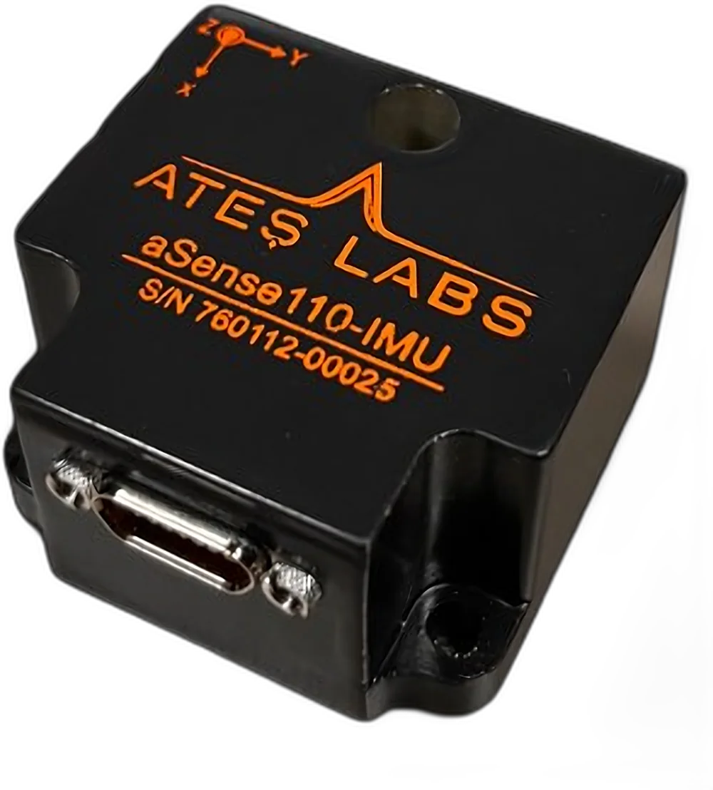 aSense110-IMU
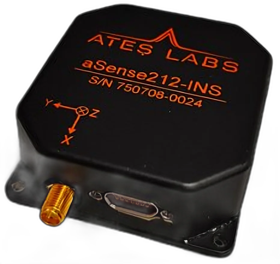 aSense210-INS
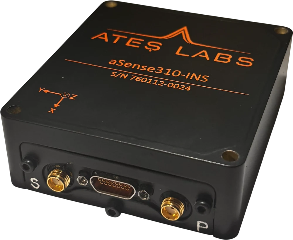 aSense310-INS
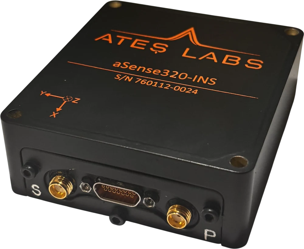 aSense320-INS
 GNSS-Denied Solution
Explore Navigation →
 SEZEN — Marine
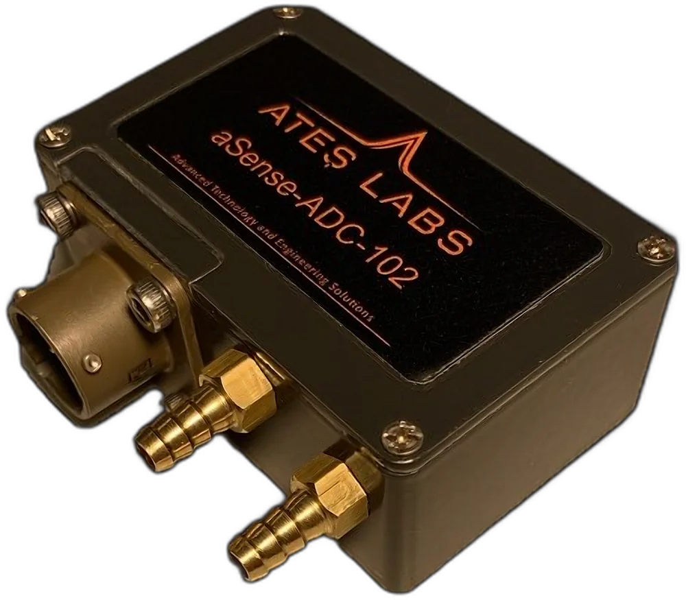 aSense ADC-TRD-102
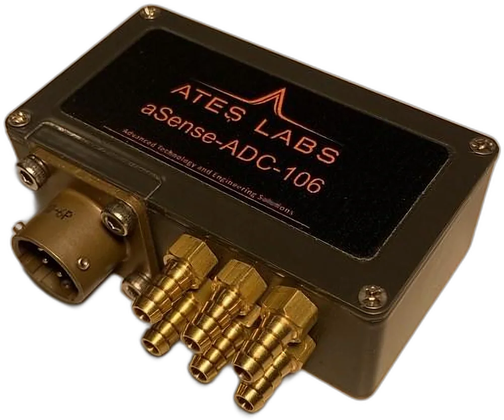 aSense ADC-TRD-106
Explore Air Data →
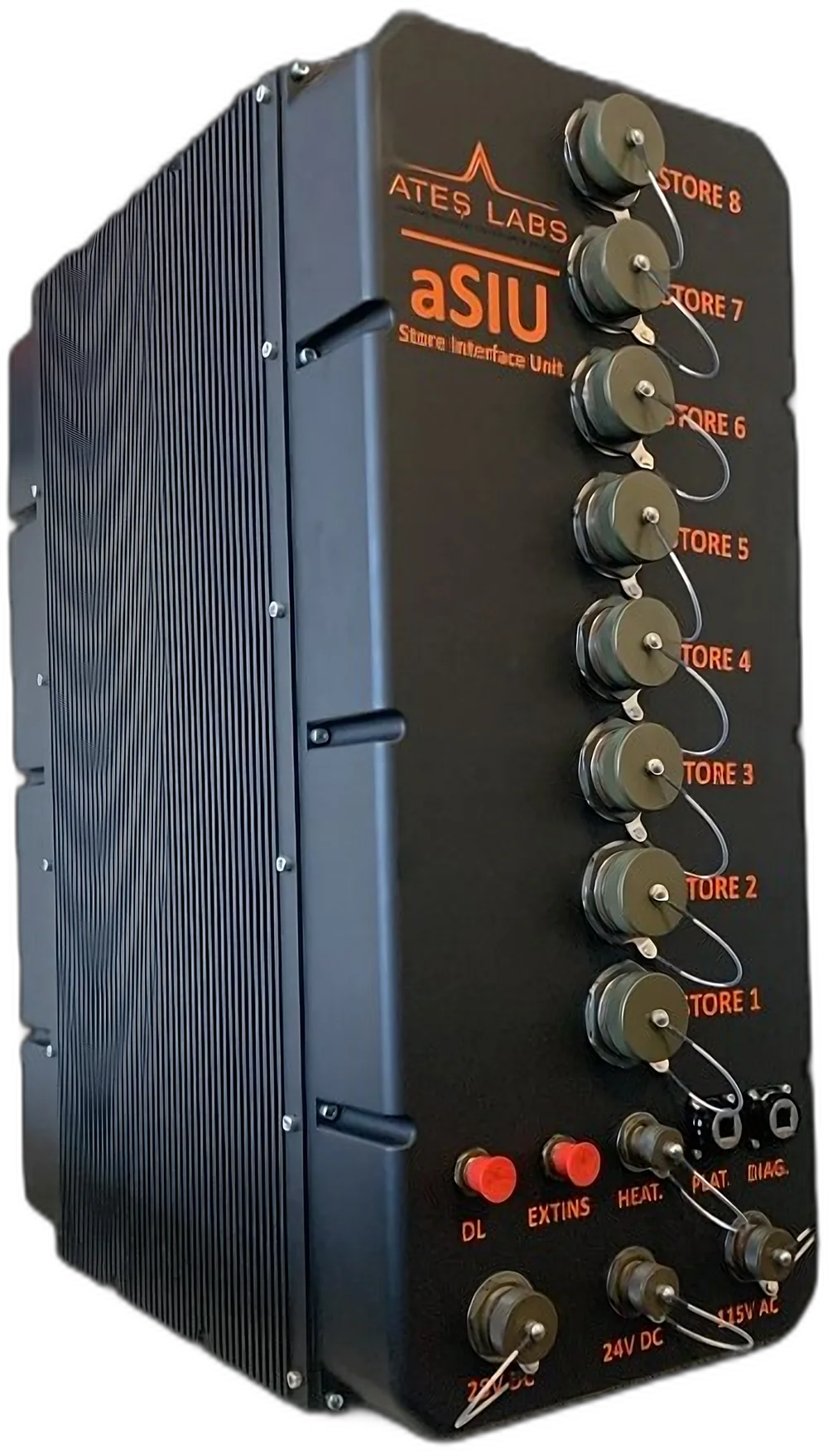 aSIU-200
 HILS-200
 Power Electronics
Explore Electronic Design →